My first control surface…let’s hope I don’t screw it up.
Rudder Stiffeners:
Jenni and I, being done with the HS and VS, moved on to the rudder. Well not instantly, but when the garage gets hot in Phoenix it’s hard if not dangerous to spend more than a few minutes out there to work on the plane. Boy – are these skins thin!
First thing was to figure out left and right on these things. Next we used the soldering iron method of removing the protective vinyl where the rudder stiffeners will go. On to fabricating the stiffeners; this is a process that I did not expect to take as long as it did. There was a lot more cutting than I expected. When I was done I had a bunch of clippings that looked like some robotic toenails.
Back riveting is interesting. You need to be sure that when you are doing multiple rivets like this, you stay on the back rivet plate. I slid the skin ever so slightly and only half the rivet was on the back rivet plate. Drilling out a half set machine head is not a fun task. In fact I had to re-dimple a hole because of that goof.
A note on fabrication:
For any of you new builders who might be looking for a simple method of fabrication of any parts, the easiest I have found is as follows:
1. Make your measurements and mark them out with a fine tip Sharpie.
2. Go back and measure them again (see screwup#1 for an explanation why)
3. Hold them where they are supposed to go to make sure you marked it with the right orientation (see screwup#1 for an explanation why)
4. Use the aluminum shears to make a rough cut within a 32nd or 16th of your line.
5. Use your Scotchbrite wheel to get the final shape and length.
6. Be sure to hit the edges after your final shaping, they will need it.
Rudder Skeleton
Another long hiatus because of summer heat delayed us even further. After Oshkosh 2005, I got fed up with being in the house when the project sits in the garage. See – Shop Upgrade for details.


Here is a picture of the rudder brace…not sure why I took it but I guess i thought it looked cool or something.
August 8, 2005
Clecoed the skeleton together and matched everything up. Drilled the skeleton and attached the rudder horn. Fabricated the shim that goes behind the rudder horn and test fitted it. I matched drilled the skeleton and brought the skins out for fitting.

Here is a picture of the rudder TE clecoed together.
Initially, I did not know whether the R901L & R skins went inside or outside the counter balance skin, but eventually after surfing the web and looking at other builder pictures, I determined that the R901L & R skins go on the outside. Although, having them go inside of the counterbalance skin seemed to make more sense because of drag; nothing that some Super Fill can’t cure.

Final drilling the rudder skins to the skeleton was interesting. I was really nervous about the training edge not coming out correctly, so I clecoed the entire TE together and alternated the cleco pattern all the way down. The trailing edge looks to be very straight so far, we will see what happens to it when I dimple/countersink it and cleco it back together.
Here I am fabricating the lower attach strips on the bench grinder. I know, I know…Where are my safety goggles?

Here is a picture of the lower attach strips after fabricating them.

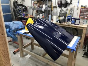
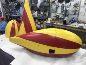
Here is a picture of the rudder clecoed together.


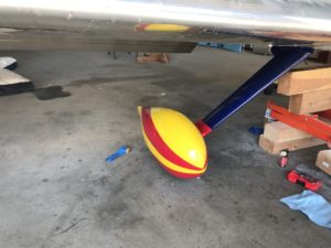
And yet another picture of the rudder and the rudder brace again.

Here I am drilling the Rudder trailing edge.

As I was calling it a night in the shop, Jenni got home and wanted to work on the plane so I pondered for a minute…I had already shut down the A/C and she suggested that we take the pieces inside so we could spend time with the birds and watch TV for a bit. So she laid out some newspaper and proceeded to debur all the rudder skeleton pieces. A quick inspection showed that she, as usual, did a fantastic job. Jenni saved me an hour worth the work.
To date she has done everything except fabricating parts on the grinder.
August 9, 2005
Dimpling Day. Jenni and I spent 2 hours tonight deburring and dimpling skins and rudder parts. The dimpling process on those tiny ribs was an interesting task. I had to make a Gonculator to get the last couple of dimples in the top rib. That was a major pain in the ass.
Here is what I did to get the trailing edge side of the top rib. First I had to take out my ‘close quarters dimple kit’ from Cleveland only to discover that its not so close quarters when you figure in the brass and steel nails that are used to squeeze the two dies together. So I grabbed some ‘shims’. Ok well actually it was my two rivet gauges from Cleveland Tools. Those were used between the flanges of the rib combined with the female die from the CQ Dimple tool so that the rib flange would not compress. I then used a flat piece of steel with a hole in it to keep from crushing the opposite flange. Thread through the provided brass nail add on the male CQ die and give it a squeeze with your blind rivet squeezer just until the resistance starts to tighten up. This starts the dimple. Then you keep this contraption together and used the steel nail so that you can finish the dimple. Repeat steps for other side. I then used my hand seamer to straighten out the flange and make sure it was still in its original shape. Per the instructions, it’s not supposed to be as good as the C-frame or hand squeezer but mine came out looking great.
“Necessity is the mother of all invention”
August 10, 2005
Finished deburring both the skins and dimpled both the skins (not the stiffners). That DRDT-2 makes short and quiet work of a dimpling task. I can work well into the night on dimpling.
Started a discussion on the email list today and was surprised at the variations of answers that I got. The question was whether the R901L & R skins go on top of or beneath the counter balance skin. According to the plans they go on top facing into the wind which made no sense to me. Long story short was that I was correctly reading the plans – the rudder skins go on top of the counter balance skins and do face into the wind. Now there is a note to taper the skin down but my plans are to go a step further and I am going to use the rudder tips as an excuse to fill the rivet line on the counter balance. With it sticking out in the wind, I would like to reduce drag as much as possible.
August 11, 2005
Testing primer: I have been using the Sherwin Williams rattle can PE-988 self-etching primer. Seems to work ok but I also picked up some of their 2-part PE-990 primer and reducer. I was hesitant about the whole mix, wait spray, etc. So I took the old HS405 and a couple of other parts outside and primed them with the two part PE-990 stuff. Boy, what a difference! This stuff is pretty damned durable and holds up like I want it to. Way better than the rattle can stuff. It also has a green tint to the grey; gives an interesting look to my primed parts.
August 12, 2005
When I got home from work, I set out and Aluma-prepped my rudder skeleton. This was an interesting job because some of the neighborhood kids were outside running around and shrieking every 30 seconds or so. I wonder if their parents would mind if I cleco clamped their mouths shut?
August 13, 2005
Priming parts today. I mixed up a pretty good sized batch of that 2 part primer. I am going to give this stuff a try since I bought it and might as well use it. The first part I sprayed was the rudder brace. It looked alright, but until it was dry and I can pick it up I would not know for sure.
½ hour later I was pleasantly surprised to see that I knew how to prime with something other than the simple rattle can. The rudder brace came out great and I decided to shoot the rest of the parts with the primer less the trailing edge and the control horn. I hit everything that I could with the primer and even hit some of the more exposed parts like the attach strips with two coats. The primer seems to be very durable and way more scratch resistant than the rattle can version.
August 14, 2005
I countersunk the holes in the rudder trailing edge. I was not too impressed with this because if you go far enough to accommodate both dimpled skins, you run the risk of enlarging the hole in the trailing edge strip. I thought about this when I first set up to work on the rudder.
After counter sinking the trailing edge, I Aluma-prepped it and hung it up to dry. I also Aluma-prepped the rudder control horn after rounding the corners ever so slightly. While I was letting them dry; I mixed up a batch of primer and then shot those two parts.
They came out ok except there must have been some contaminant in the spray gun canister. There were a bunch of little flecks that showed up after shooting the parts. Crap!! I am going to sand those tomorrow or the next day. I have some sand paper that I used with plastic models that is like a bazillion grit sand paper that should get those out without scratching the parts.
August 19, 2005
I was working my day job for quite a while and then had to tend to the house so I was not able to get as many hours in the shop as I wanted. I used the 600 grit sandpaper to remove the contaminants that were embedded in the trailing edge and smoothed it out just fine. I touched it up with the rattle can primer. Jenni asked me if the two different color primers bothered me. Uh…no it doesn’t; the rattle can primer and the two-part primer I have now are both Sherwin Williams self etching primer that do the same job. The two-part primer seems to be a bit more durable but is as expensive as hell. It’s $75 for a 1 qt can of primer and 1 qt can of etcher/reducer. After doing the math – I decided that I am going to go with the AKZO two-part primer because of the cost of the Sherwin Williams product.
August 20, 2005
Assemble – Squeeze Rivet – Oh Shit – Drill Out Rivet – Repeat
That was the theme of today; I almost did not work too much on the plane because my focus was just off. However, I spent 12 hours in the shop when the day was done. My first mistake was a real dummy maneuver. When I was squeezing on the rivets for the rudder spar reinforcements I got going so good that I started to squeeze the lower reinforcement less the rudder brace, horn, shim, etc. This frustrated the hell out of me and I was about ready to call it a day. So I drilled out those rivets and re-primed the reinforcement bracket. I gathered my wits but not all of the parts and started over. The reinforcement plate was on the other side of the shop, out of sight and out of mind. Drill out two more rivets. Next when I was putting all the parts on I managed to squeeze a rivet where the nutplate was supposed to get riveted in….Geez Louise!! This is getting bad! I stopped what I was doing and ate some lunch. After lunch I came back out and tried it again. Despite my earlier frustration – I eventually got it all right with all of the correct rivets and all of the parts where they were supposed to be. I TRIPLE checked everything this time. The spar was now riveted correctly with the reinforcement plates and nutplates in place.
I riveted on the counterweight rib and skin then torqued in the counterweight after some aggressive filing with the Vixen file. Well OK, it was Jenni who torqued in the counterweight. I was nearing that moment of truth where all this work could be for naught if something pushed my trailing edge out too far. I clecoed the skins on and squeezed those rivets that I could reach with the yoke. There were 6 or 7 rivets that had to be bucked on the counterbalance skin and a few more on the right skin down by the bottom of the rudder. I used blind rivets on the last two rib to skin attachments that were closest to the trailing edge on both the top and bottom. All in all, this thing was starting to look pretty good.
Ok…So I had been scouring the web for some time looking for trailing edge gotcha’s and found a site that explained a pretty interesting method for getting the TE straight. It showed a way of back riveting about ½ way down on every other rivet (working out from center). Then you go back and do the same to the remaining rivets. There are other builders who have worked the TE riveting one on the left and one on the right. That seemed like too much moving around and change for tweaking. I opted for the every other rivet idea checking the straightness frequently.
I measured with a straightedge and found there to be 0.050” runout. That is 50% of the allowable max runout for the trailing edge as spoken by Van’s. Now I know that they use some suggestive words rather than mandating but they say to shoot for .100” runout. Is it perfect? No, Is it more than acceptable? By at least 50%.
The leading edge did not give me too much trouble although it took a couple tries with different sized dowels to get it where I wanted it. I drilled and pop-riveted the leading edge to call the Rudder complete. YEEE HA!
Why did it take me so long to complete this? Frankly because we have lots of other projects going on around the house, summers are hot and you need to cool the work area, and I have been very busy at work and if you skip a day, it gets easier to skip another day and another, and so on.